Windows Telephony Overview

Connection Model Independence


The layer of abstraction between applications and hardware that TAPI provides allows for a single programming model no matter how the hardware has been connected to the user's PC. The TAPI Specification lists several possible examples of connection models. Ultimately, however, as long as the programming model remains consistent, a hardware vendor is free to provide a connection in any way that makes sense. Several of the popular connection models are described below.


Phone-Centric Connection


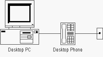
Figure 5: Phone-Centric Connection Model


The phone-centric model is the one most liked by people in the phone hardware business. The focus on this model, as the name states, is the phone. The phone line from the wall is connected to the desktop phone. Then phone is then connected to the PC via some kind of digital connection. The phone controls the calls and the PC directs the phone. For example, the AT&T 8130 is a two-line phone that connects to the PC via a serial cable. It comes with a TSP that provides access to both phone lines. However, the phone has a lot of features - Caller-ID display, speed dial memory, hold, mute, volume, et cetera - all of which are available without help from the PC.

This model works equally well for whatever kind of phone - POTS, Centrex, ISDN, PBX-specific, cellular - the computer is connected to. To get most of the functionality out of the phone in this model, the PC doesn't even have to be on.


Computer-Centric Connection


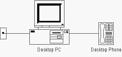
Figure 6: Computer-Centric Connection Model


PC manufacturers like the computer-centric connection model. In this model, the phone line is connected directly to the computer via some telephony hardware like a modem or an ISDN adapter card. The computer is the brains of this model and the phone (sometimes called the down-line phone) simply acts as a microphone and speaker. In this model, the PC essentially replaces the phone. Of course, for this to work, the PC has to be on.

Windows 95 and Windows NT 4.0 come with a built-in TSP called Unimodem. This TSP has a giant database of modem-specific AT commands to direct a modem through a phone call. Because most modem hardware is limited when it comes to voice calls, however, Unimodem makes a poor TSP. Some modems provide voice support via proprietary extensions or by implementing an AT command extension set called AT+V (AT plus Voice). The TSP Unimodem/V provides special support for these voice modems.


LAN Connection


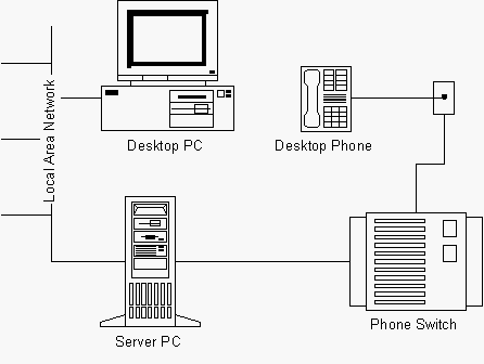
Figure 7: LAN Connection Model


In this model, the desktop PC and the phone aren't even directly connected. Instead, a server on the LAN connects to the phone switch - a PBX - via some kind of digital link. The desktop PC connects to the server via the LAN and directs it to control calls. The server passes these commands to the switch which controls the phone on the same desktop as the PC. Unlike the previous two models, which use 1st-party call control, this is a 3rd-party call control model.


What Happened To The 2nd Party?

Each connected phone call has at least two parties, one on each end. Each party, whether a person or a computer, has control of one end of the call. 1st-party call control means that the control of the call rests solely with the party participating on the call. No one else controls the connection. If the call is transferred somewhere else, control is lost and given to the transferee. 3rd-party call control, however, means that the end-point of the call shares control with another.

For example, in the LAN connection model, the end-point of the call is the desktop phone, which has 1st-party control. The desktop PC has 3rd-party call control by talking to the switch, via the server PC, to control the call. This means that you could disconnect your end of the call by hanging up the phone (1st-party call control) or by sending a hang-up signal to the switch from your desktop PC (3rd-party call control).

What about 2nd-party call control? There is no such thing.


For the LAN connection model, the TSP provided on the desktop PC is not talking to a phone, but rather to the server PC on the LAN. This model typically limits access to the data on the call. The bandwidth required to send data or voice between the switch and the server PC and between the server PC and the desktop PC isn't that much. However, when combined with existing LAN traffic and multiplied by everyone on the phone, access to the data on a phone call is a luxury most LAN and switch managers are not willing to provide.

The main benefit of this model is that no additional hardware is required on the desktop PC to make it work. A desktop PC connected to the LAN can control the desktop phone with some additional software - specifically a TSP. Once the server PC is connected to the switch, everyone can control their phone from their desktop.


Client/Server Connection


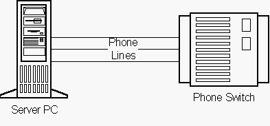
Figure 8: Client/Server Connection Model


This model is used for IVR applications. A bank that needs to provide account information to its customers or an automated operator run by the local phone company will use this model. The server PC is connected to the switch by several phone lines. The server PC controls the calls on these lines using 1st-party call control. It can play messages, take input and provide information. You can think of these systems just like any other kind of PC server, except instead of using a local area network connection to communicate with its clients, it uses a telephone network connection.


Back | Top | Next